Developing CFU-Playground with Renode
Renode is an open source simulation framework provided by Antmicro that lets you simulate complex hardware devices and allows you to run the same software you’d normally run on hardware. A machine can contain various components, including the ones configured on FPGA chips.
Renode’s ability to co-simulate with Verilated code allows CFU Playground users to test their ML accelerators and their software in a deterministic, easily debuggable and fully controlled environment without even having to ever see the target FPGA board and without the need to verilate the whole SoC.
For more information, consult the Renode documentation.
Prerequisites
To start simulation of your project with Renode you need to set up your machine for building projects first.
Renode itself is installed by default during the CFU Playground’s setup. Follow the documentation to properly prepare your machine. Don’t worry if you don’t have a board necessary for the last “Step 6: Test Run” step of the setup guide. You can treat Running your project with Renode as a test run step for working with Renode.
You can build and simulate your project in Renode without having any FPGA toolchain installed.
Renode accurately models the memory resources available on a specific board, specified using TARGET=<board>.
Example target boards you can pass to make commands with TARGET= include:
icebreakerto choose a Lattice FPGA-based iCEBreaker board by 1BitSquared,digilent_artyto choose a Xilinx FPGA-based Arty A7-35T board by Digilent.
By default, if you don’t set the TARGET variable, projects are built for the Arty A7 board.
Note
If you used Conda to set up your machine, make sure to have the cfu-common environment activated before running any make commands.
You can check if it’s been activated properly with the conda env list command which should print cfu-common followed by an asterisk:
$ conda env list
# conda environments:
#
base                     <...>/CFU-Playground/env/conda
cfu-common            *  <...>/CFU-Playground/env/conda/envs/cfu-common
Running your project with Renode
Simulating your project in Renode is quite straightforward.
Such an option is embedded in the Makefile configurations of proj_template so in all projects based on it all you need to do is run the make renode command in the project’s directory.
For example you can simulate the example_cfu project in Renode by running these commands from the CFU-Playground’s root directory:
CFU-Playground $ cd proj/example_cfu
CFU-Playground/proj/example_cfu $ make renode  # Use 'make renode-headless' to run Renode without GUI.
Note
In case of a failure, e.g., due to the “ModuleNotFoundError: No module named ‘nmigen’” or “OSError: Unable to find any of the cross compilation toolchains” errors, make sure you followed the Prerequisites closely.
The project will be built the first time you run it in Renode. Then the Renode’s monitor and analyzer (for UART communication) windows should open. The simulation logs will be output to the shell terminal Renode has been started from.
To exit Renode, type quit at the prompt in the monitor window.
Using Renode without GUI
If you wish to run Renode without GUI, use the make’s renode-headless target instead of the renode target.
In a headless mode (more precisely: a console headless mode), the Renode’s Monitor and an analyzer for the UART communication share the input and output streams.
Switching between the Monitor and UART is pretty straightforward in Renode.
By default, you will be connected to a UART session after running make renode-headless.
You can switch to the Monitor by pressing the <ESC> key.
After running some Renode commands you can return to the UART session with the uart_connect sysbus.uart command.
Note
Renode simulation logs in a headless mode are suppressed by default for a readable Monitor and UART communication.
To save logs to a file, use the Renode’s logFile @some_file_name command.
Make sure you have switched to the Monitor before entering the command.
Note
Switching between the Monitor and UART is an action the software isn’t aware of.
Therefore after switching back to UART you might not see its latest output.
You can, however, refresh the UART output by pressing <ENTER>.
Attaching GDB
You can use the GNU debugger with your project running in Renode.
The Renode script generated by CFU-Playground’s Makefile starts the GDB server on the local 10001 port by default.
Therefore after running GDB with build/software.elf executable, you can attach it to Renode with the target remote :10001 command.
Remember to use step[i] N, next[i] N or continue in GDB for the simulation to advance.
The software won’t react to UART interaction when GDB awaits the user input.
An example of checking RISC-V registers with GDB for Renode running the example_cfu project on a simulated 1BitSquared iCEBreaker board:
CFU-Playground/proj/example_cfu $ riscv32-elf-gdb build/software.elf
GNU gdb ...
...
Reading symbols from software.elf...
# Run 'make renode' or 'make renode-headless' from a different shell before running the 'target remote' command.
(gdb) target remote :10001
Remote debugging using :10001
0x8009f918 in uart_read_nonblock () at CFU-Playground/third_party/python/litex/litex/soc/software/libbase/uart.c:75
75          return (rx_consume != rx_produce);
(gdb) br bit_reverse
Breakpoint 1 at 0x80031d0c: file src/software_cfu.cc, line 28.
(gdb) continue
Continuing.
# Started a 'hw/sw compare tests' (2 -> c) through Renode.
Breakpoint 1, 0x80031d0c in (anonymous namespace)::bit_reverse (rs1=<optimized out>)
at src/software_cfu.cc:28
28      rs2 >>= 8;
(gdb) info all-registers
zero           0x0  0
ra             0x80030bd4   0x80030bd4 <(anonymous namespace)::do_compare_tests()+188>
sp             ...
...
Note
Your GDB might have a different name, e.g. riscv64-unknown-elf-gdb.
It depends on how you installed the RISC-V toolchain or the GDB itself but as long as it targets the RISC-V ISA it should work well.
Creating a trace of the execution
A trace of the execution can be created in Renode using the LogFunctionNames command on the CPU peripheral (sysbus.cpu).
Names of the functions will be printed to a log during execution.
For example after running these commands in the Monitor:
Renode, version 1.12.0.4321 (47a5d2ff-202201210224)
(monitor) s @icebreaker.resc  # This command is run automatically by 'make renode'.
(icebreaker) logFile @test.log
(icebreaker) sysbus.cpu LogFunctionNames true true
Renode will print an address and a function name with each function change during the simulation (the “comments” show external actions which influence the log):
# Monitor: Executing 'logFile' and 'LogFunctionNames' commands.
11:55:59.2861 [INFO] icebreaker: Machine paused.
11:55:59.2862 [INFO] icebreaker: Machine resumed.
11:55:59.3868 [INFO] cpu: Entering function litex_getc at 0x8009F910
# UART: Writing '8'.
11:56:12.8248 [INFO] cpu: Entering function trap_entry (entry) at 0x8009F6DC
11:56:12.8248 [INFO] cpu: Entering function trap_handler (entry) at 0x80030020
11:56:12.8249 [INFO] cpu: Entering function uart_isr (entry) at 0x8009FAE4
11:56:12.8250 [INFO] cpu: Entering function trap_entry+0x84 (guessed) at 0x8009F760
11:56:12.8250 [INFO] cpu: Entering function litex_getc at 0x8009F910
11:56:12.8251 [INFO] cpu: Entering function getc at 0x800A5538
11:56:12.8251 [INFO] cpu: Entering function readchar at 0x80030848
...
Note
You can omit the logFile command if you run Renode with GUI.
Unless the log is hidden explicitly it will be printed to the console Renode was started from.
You can find more information, e.g. on how to filter functions by their names, in the Renode’s logging documentation.
Generating Verilator waveforms (traces)
Generating waveform (trace) files is an optional feature of the Verilator simulation.
The build system for Renode Verilated blocks (see common/renode-verilator-integration/CMakeLists.txt and proj/proj.mk) supports generating such waveform files.
To have a standard VCD waveform generated by Verilator, set Makefile’s ENABLE_TRACE_ARG variable to --trace.
To have an optimized GTKWave’s FST files generated, set the variable to the --trace-fst value instead.
The optional depth of tracing can be set with Makefile’s VERILATOR_TRACE_DEPTH variable.
When used without the ENABLE_TRACE_ARG argument, the latter will automatically be set to --trace.
By default, trace files are saved either as build/simx.vcd if the --trace argument was used or as build/simx.fst for --trace-fst.
You can change the default path of the trace files using Makefile’s VERILATOR_TRACE_PATH variable.
For example, the FST trace of only the top signals will be generated as /tmp/vtrace during the simulation if you use such a command to run your project with Renode:
CFU-Playground/proj/my_project $ make ENABLE_TRACE_ARG=--trace-fst VERILATOR_TRACE_DEPTH=1 VERILATOR_TRACE_PATH=/tmp/vtrace.fst renode
Note
With the FST format there’s always also the additional *.hier file generated.
Automated testing
Renode’s integration with Robot Framework makes it possible to run automated project tests based on test cases defined in the .robot files.
Run the renode-test Makefile target from a project’s directory to run tests for the given board and project.
For example, you can run the example_cfu Robot tests on an Arty A7 board simulated by Renode with:
CFU-Playground/proj/example_cfu $ make renode-test
# Building project for the given target and generating Renode scripts.
...
Running <path>/proj/example_cfu/build/renode/digilent_arty.robot
+++++ Starting test 'digilent_arty.Should Walk The Menu'
+++++ Finished test 'digilent_arty.Should Walk The Menu' in 4.23 seconds with status OK
Cleaning up suites
Closing Renode pid 166260
Aggregating all robot results
Output:  <path>/proj/example_cfu/robot_output.xml
Log:     <path>/proj/example_cfu/log.html
Report:  <path>/proj/example_cfu/report.html
Tests finished successfully :)
The Robot file for, e.g., my_project has to be placed as my_project.robot in the project’s root directory.
This will be a default Renode test definition file for all targets.
Format of the Robot files is quite verbose so analyzing other project’s Robot files is a good way for a quick start (see, e.g., the mnv2_first’s main Robot file).
Note
Use the TARGET placeholder wherever target’s name is expected, such as when including the Renode Script file name (.resc):
Execute Command include @${CURDIR}/TARGET.resc
If a target, e.g. my_target, needs to have a dedicated Robot file besides using TARGET, you can add such a file as proj/my_project/renode/my_target.robot.
The target-dedicated Robot files are prioritized over the ones default for the project placed in its root directory.
The tests can be run directly with Renode test script, which, e.g., allows passing custom flags to the test engine.
For example, you can run just the Should Run TFLite Unit Tests test case from the mnv2_first project’s Robot file repeatedly 10 times on an Arty A7 target with:
CFU-Playground/proj/mnv2_first $ make renode-scripts
# Building project for the given target and generating Renode scripts.
...
CFU-Playground/proj/mnv2_first $ ../../third_party/renode/renode-test -n 10 -f "TFLite Unit Tests" build/renode/digilent_arty.robot
Testing fixture: TFLite Unit Tests
Preparing suites
Started Renode instance on port 9999; pid 206191
Starting suites
Running tests iteration 1 of 10...
Running build/renode/digilent_arty.robot
+++++ Starting test 'digilent_arty.Should Run TFLite Unit Tests'
+++++ Finished test 'digilent_arty.Should Run TFLite Unit Tests' in 1.70 seconds with status OK
Running tests iteration 2 of 10...
...
Note
If you run Renode tests directly, remember to first run the renode-scripts Makefile target to build a project for the given board.
For more information, check out Renode’s testing documentation and Robot Framework’s documentation. For more examples, take a look at many Robot test definition files available in Renode.
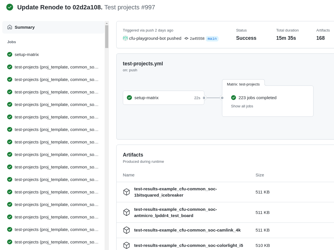
Testing with GitHub Actions
Correctness of the CFU-Playground project is ensured with Renode simulating various targets in the Github Actions “Test projects” workflow. The workflow internally uses the “Test in Renode” GitHub Action.
Testing is conducted for each project-board pair from the matrix generated by the generate_ci_matrix.py script.
Such a pair is created with each project from the projects_to_test.txt file and each target from the supported_targets.txt file unless the target is listed in the given project’s ci/ci_exclude_targets.txt (e.g. the proj_template’s one).
Therefore to add a new project, e.g. my_project, to be tested in CI:
place the project in the
proj/my_projectdirectory,add a
my_projectline to the.github/workflows/projects_to_test.txtfile,add a Robot file for Renode as
proj/my_project/my_project.robot,optionally, for each
special_targetwhich requires their own Robot file, add aproj/my_projects/renode/special_target.robotfile (see for example mvn2_first/renode/hps.robot file),optionally, add a
proj/my_project/ci/ci_exclude_targets.txtfile where each line is a target excluded from testing.
To add a new target, e.g. my_target, to be tested in CI:
add a
my_targetline to the.github/workflows/supported_targets.txt,for each
.github/workflows/projects_to_test.txtproject which you don’t want to be tested on the given target, add amy_targetline to the project’sci/ci_exclude_targets.txt.